东软载波单片机HR8P506驱动TFT SPI串口屏显示
1、【1】打开Keil uVision5建立好相应的工程项目,添加相应的文件和头文件路径,在建立工程过程中需要使用Keil插件,可到官网去下载,亦可联系我。
【2】.初始化SPI GPIO配置。SPI_MOSI、SPI_MISO、SPI_SCK、SPI_CS配置为复用输出模式,SPI_CS亦可配置为普通输出模式。若是使用模拟SPI方式直接配置为普通模式输出即可。
#define TFT_SPI0_MOSI_PinGPIO_Pin_A13
#define TFT_SPI0_MISO_PinGPIO_Pin_A12
#define TFT_SPI0_SCK_PinGPIO_Pin_A11
#define TFT_SPI0_CS_PinGPIO_Pin_A10
static void vTFT_SPI0_GPIO_Configuration(void)
{
GPIO_InitSettingType GPIO_InitStructure;
GPIO_InitStructure.Signal = GPIO_Pin_Signal_Digital;//Digital Pin
GPIO_InitStructure.Dir = GPIO_Direction_Output;//Output mode
GPIO_InitStructure.Func = GPIO_Reuse_Func3;//Reuse functio3
GPIO_InitStructure.ODE = GPIO_ODE_Output_Disable;//Open drain disable
GPIO_InitStructure.DS = GPIO_DS_Output_Strong;//Strong output
GPIO_InitStructure.PUE = GPIO_PUE_Input_Disable;//Pull up disable
GPIO_InitStructure.PDE = GPIO_PDE_Input_Disable;//Pull Down disable
GPIO_Init(TFT_SPI0_MISO_Pin, &GPIO_InitStructure);//Init TFT_SPI0_MISO_Pin
GPIO_Init(TFT_SPI0_MOSI_Pin, &GPIO_InitStructure);//Init TFT_SPI0_MOSI_Pin
GPIO_Init(TFT_SPI0_SCK_Pin, &GPIO_InitStructure);//Init TFT_SPI0_SCK_Pin
GPIO_InitStructure.Signal = GPIO_Pin_Signal_Digital;//Digital Pin
GPIO_InitStructure.Dir = GPIO_Direction_Output;//Output mode
GPIO_InitStructure.Func = GPIO_Reuse_Func0;//Reuse functio0
GPIO_InitStructure.ODE = GPIO_ODE_Output_Disable;//Open drain disable
GPIO_InitStructure.DS = GPIO_DS_Output_Strong;//Strong output
GPIO_InitStructure.PUE = GPIO_PUE_Input_Disable;//Pull up disable
GPIO_InitStructure.PDE = GPIO_PDE_Input_Disable;//Pull Down disable
GPIO_Init(TFT_SPI0_CS_Pin, &GPIO_InitStructure);//Init TFT_SPI0_CS_Pin
}
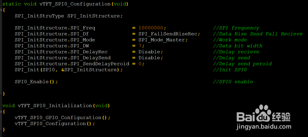
【3】配置SPI。SPI频率、数据格式、通讯模式、发送帧位宽、延时接收使能、发送间隔使能、发送间隔周期。若使用模拟SPI方式此步骤可以忽略,最后初始化SPI。
static void vTFT_SPI0_Configuration(void)
{
SPI_InitStruType SPI_InitStructure;
SPI_InitStructure.SPI_Freq = 10000000;//SPI frequency
SPI_InitStructure.SPI_Df = SPI_FallSendRiseRec;//Data Rise Send Fall Recieve
SPI_InitStructure.SPI_Mode = SPI_Mode_Master;//Work mode
SPI_InitStructure.SPI_DW = 7;//Data bit width
SPI_InitStructure.SPI_DelayRec = Disable;//Delay recieve
SPI_InitStructure.SPI_DelaySend = Disable;//Delay send
SPI_InitStructure.SPI_SendDelayPeroid = 0;//Delay send peroid
SPI_Init(SPI0, &SPI_InitStructure);//Init SPI0
SPI0_Enable();//SPI0 enable
}
void vTFT_SPI0_Initialization(void)
{
vTFT_SPI0_GPIO_Configuration();
vTFT_SPI0_Configuration();
}
【4】配置TFT GPIO。TFT_RESET、TFT_RS配置为普通模式输出。
#define TFT_RESET_PinGPIO_Pin_A15
#define TFT_RS_PinGPIO_Pin_A14
static void vTFT_GPIO_Configuration(void)
{
GPIO_InitSettingType GPIO_InitStructure;
GPIO_InitStructure.Signal = GPIO_Pin_Signal_Digital;//Digital Pin
GPIO_InitStructure.Dir = GPIO_Direction_Output;//Output mode
GPIO_InitStructure.Func = GPIO_Reuse_Func0;//Reuse function 0
GPIO_InitStructure.ODE = GPIO_ODE_Output_Disable;//Open drain disable
GPIO_InitStructure.DS = GPIO_DS_Output_Normal;//Normal Output
GPIO_InitStructure.PUE = GPIO_PUE_Input_Disable;//Pull up disable
GPIO_InitStructure.PDE = GPIO_PDE_Input_Disable;//Pull Down disable
GPIO_Init(TFT_RESET_Pin, &GPIO_InitStructure);//Init TFT_RESET_Pin
GPIO_Init(TFT_RS_Pin, &GPIO_InitStructure);//Init TFT_RS_Pin
}


2、【1】编写写指令、写数据函数,这两个函数是最核心的函数。若使用模拟SPI方式,重点也是修改这两个函数。
#define TFT_CS_SET()GPIO_SetBit(TFT_SPI0_CS_Pin)
#define TFT_CS_CLR()GPIO_ResetBit(TFT_SPI0_CS_Pin)
#define TFT_RS_SET()GPIO_SetBit(TFT_RS_Pin)
#define TFT_RS_CLR()GPIO_ResetBit(TFT_RS_Pin)
写字节命令函数
void vTFT_WriteByte_Command(u8 cmd)
{
TFT_CS_CLR();
TFT_RS_CLR();
SPI_SendByte(SPI0, cmd);
while(SPI_GetStatus(SPI0, SPI_STA_IDLE) == RESET);
TFT_CS_SET();
}
写字节数据函数
void vTFT_WriteByte_Data(u8 dat)
{
TFT_CS_CLR();
TFT_RS_SET();
SPI_SendByte(SPI0, dat);
while(SPI_GetStatus(SPI0, SPI_STA_IDLE) == RESET);
TFT_CS_SET();
}
写u16数据函数
void vTFT_Write_Data(u16 dat)
{
TFT_CS_CLR();
TFT_RS_SET();
SPI_SendByte(SPI0, (u8)(dat >> 8));
while(SPI_GetStatus(SPI0, SPI_STA_IDLE) == RESET);
SPI_SendByte(SPI0, (u8)dat);
while(SPI_GetStatus(SPI0, SPI_STA_IDLE) == RESET);
TFT_CS_SET();
}


3、【1】配置滴答定时器做延时使用,有毫秒级和微秒级的延时,最低10us的倍数延时。
滴答定时器为24Bit倒计时计数器,属于内核定时器,在ARM Cortex-M0/M3/M4上都有。
u8 Fac_us = 0;
u16 Fac_ms = 0;
void vSysTick_Delay_Initialization(void)
{
SYSTICK_InitStruType SysTick_InitStructure;
Fac_us = (SystemCoreClock / 3000000) * 10;//SysTick Value=10us
Fac_ms = Fac_us * 100;//1ms
SysTick_InitStructure.SysTick_ClkSource = SysTick_ClkS_Base;//SysTick colck = Hclk/3 = 16M
SysTick_InitStructure.SysTick_ITEnable = Disable;//Disable SysTick interrupt
SysTick_Init(&SysTick_InitStructure);//Init SysTick
}
毫秒级延时
void Delay_ms(u16 Nms)
{
u32 Temp = 0;
SysTick->LOAD = (u32)Nms*Fac_ms;//Auto Reload value
SysTick->VAL = 0X00;//SysTick Current Value
SysTick->CTRL |= SysTick_CTRL_ENABLE_Msk;//Enable SysTick
do
{
Temp = SysTick->CTRL;
}
while((Temp&0x01) && (!(Temp&(1<<16))));//Enable SysTick and count non-arrival
SysTick->CTRL &= ~SysTick_CTRL_ENABLE_Msk;//Disable SysTick
SysTick->VAL = 0X00;//SysTick Current Value
}
10微秒级延时
void Delay_10us(u32 Nus)
{
u32 Temp = 0;
SysTick->LOAD = (u32)Nus*Fac_us;//Auto Reload value
SysTick->VAL = 0X00;//SysTick Current Value
SysTick->CTRL |= SysTick_CTRL_ENABLE_Msk;//Enable SysTick
do
{
Temp = SysTick->CTRL;
}
while((Temp&0x01)&& (!(Temp&(1<<16))));//Enable SysTick and count non-arrival
SysTick->CTRL &= ~SysTick_CTRL_ENABLE_Msk;//Disable SysTick
SysTick->VAL = 0X00;//SysTick Current Value
}


4、【1】编写TFT出厂参数校准函数,这个函数里才参数都是有TFT LCD厂家调试好的参数,直接拿过来用就行,需要设置的参数比较多,这里只展示一部分。
static void vTFT_Default_Set(void)
{
TFT_RESET_CLR();
Delay_ms(500);
TFT_RESET_SET();
Delay_ms(100);
TFT_CS_CLR();
vTFT_WriteByte_Command(0xCB);
vTFT_WriteByte_Data(0x39);
vTFT_WriteByte_Data(0x2C);
vTFT_WriteByte_Data(0x00);
vTFT_WriteByte_Data(0x34);
vTFT_WriteByte_Data(0x02);
vTFT_WriteByte_Command(0x36);//Memory Access Control
#if ( TFT_DISPLAY_MODE_LEVEL > 0 )//横屏 竖屏选择
vTFT_WriteByte_Data(0xE8);
#else
vTFT_WriteByte_Data(0x48);
#endif
vTFT_WriteByte_Command(0x3A);
vTFT_WriteByte_Data(0x55);
.......
}

5、【1】设置光标位置
void vTFT_SetCursor_Position(u16 x, u16 y)
{
vTFT_WriteByte_Command(0x2A);//Set X Line
vTFT_WriteByte_Data(x>>8);
vTFT_WriteByte_Data(x&0XFF);
vTFT_WriteByte_Command(0x2B); //Set Y Row
vTFT_WriteByte_Data(y>>8);
vTFT_WriteByte_Data(y&0XFF);
}
【2】绘制窗口
void vTFT_Set_Window(u16 x0, u16 y0, u16 x1, u16 y1, u16 color)
{
u16 x = 0;
u16 y = 0;
vTFT_WriteByte_Command(0x2A);//Set X Line
vTFT_WriteByte_Data(x0>>8);
vTFT_WriteByte_Data(x0&0xFF);
vTFT_WriteByte_Data(x1>>8);
vTFT_WriteByte_Data(x1&0xFF);
vTFT_WriteByte_Command(0x2B);//Set Y Row
vTFT_WriteByte_Data(y0>>8);
vTFT_WriteByte_Data(y0&0xFF);
vTFT_WriteByte_Data(y1>>8);
vTFT_WriteByte_Data(y1&0xFF);
vTFT_WriteByte_Command(0x2C);//Write GRAM
for(x=x0; x<=x1; x++)
{
for(y=y0; y<=y1; y++)
vTFT_Write_Data(color);
}
}
【3】画点函数
void vTFT_Drawing_Point(u16 x, u16 y, u16 color)
{
vTFT_SetCursor_Position(x, y);
vTFT_WriteByte_Command(0x2C);
vTFT_Write_Data(color);
}
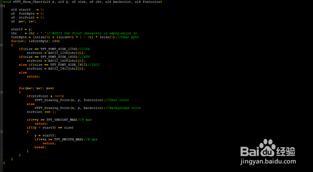
【4】在指定位置显示一个字符,可设置背景色和前景色,共有三种字体选择
void vTFT_Show_Chars(u16 x, u16 y, u8 size, u8 chr, u16 backcolor, u16 fontcolor)
{
u16 startY = 0;
u8 fontByte = 0;
u8 strPoint = 0;
u8 m=0, i=0;
startY = y;
chr = chr - ' ';//ASCII the first character is empty,value 32
fontByte = ((size/8) + ((size%8) ? 1 : 0)) * (size/2);//Char Byte
for(i=0; i<fontByte; i++)
{
if(size == TFT_FONT_SIZE_1206)//1206
strPoint = ASCII_1206[chr][i];
if(size == TFT_FONT_SIZE_1608)//1608
strPoint = ASCII_1608[chr][i];
else if(size == TFT_FONT_SIZE_2412)//2412
strPoint = ASCII_2412[chr][i];
else
return;
for(m=0; m<8; m++)
{
if(strPoint & 0x80)
vTFT_Drawing_Point(x, y, fontcolor);//Char color
else
vTFT_Drawing_Point(x, y, backcolor);//Background color
strPoint <<= 1;
if(++y >= TFT_YHEIGHT_MAX)//Y max
return;
if((y - startY) == size)
{
y = startY;
if(++x >= TFT_XWIDTH_MAX)//X max
return;
break;
}
}
}
}
【5】在指定位置显示字符串,超出范围可自动换行显示,可设置背景色和前景色,共有三种字体选择。
void vTFT_Show_Sting(u16 x, u16 y, u8 size, u8 *pstr, u16 backcolor, u16 fontcolor)
{
while((*pstr >= ' ') && (*pstr <= '~'))//while('\n' != *PSting)
{
if((x + size/2) > TFT_XWIDTH_MAX)//Next char start position
{
x = 0;
y = y + size;//Next Fong High
}
if((y + size) > TFT_YHEIGHT_MAX)
return;
vTFT_Show_Chars(x, y, size ,*pstr, backcolor, fontcolor);//TFT Show Char
x = x + size/2;
pstr++;//Next char
}
}


6、【1】
在指定位置显示数字,
static u32 uxTFT_Resolve_Num(u8 m, u8 n)
{
u32 result=1;
while(n--)
result *= m;
return result;
}
void vTFT_Show_Number(u16 x, u16 y, u8 size, u32 num, u8 len, u16 backcolor, u16 fontcolor)
{
u8 i,temper = 0;
for(i=0; i<len; i++)
{
if((x + size/2) > TFT_XWIDTH_MAX)//Next char start position
{
x = 0;
y = y + size;//Next Fong High
}
if((y+ size) > TFT_YHEIGHT_MAX)
return;
temper = (num/uxTFT_Resolve_Num(10, len-i-1))%10;
vTFT_Show_Chars(x, y, size ,(temper + '0'), backcolor, fontcolor);
x = x + size/2;
}
}

7、【1】配置系统时钟为48MHZ,使能需要的外设时钟,失能不需要的外设时钟,着这样可以降低功耗。
static void vPeripheral_Clock_Configuration(void)
{
DeviceClock_Config(SCU_SUCCLK, Enable);//Enable SUC clock
DeviceClock_Config(SCU_GPIOCLK, Enable);//Enable GPIO clock
DeviceClock_Config(SCU_SPIOCLK, Enable);//Enable SPI0 clock
DeviceClock_Config(SCU_UART1CLK, Enable);//Enable UART1 clock
DeviceClock_Config(SCU_T16N2CLK, Enable);//Enable T16N2 clock
DeviceClock_Config(SCU_IAPCLK, Disable);//Disable IAP clock
DeviceClock_Config(SCU_T16N0CLK, Disable);//Disable T16N0 clock
DeviceClock_Config(SCU_T16N3CLK, Disable);//Disable T16N3 clock
DeviceClock_Config(SCU_UART0CLK, Disable);//Disable UART0 clock
DeviceClock_Config(SCU_WDTCLK, Disable);//Disable WDT clock
DeviceClock_Config(SCU_T16N1CLK, Disable);//Disable T16N1 clock
DeviceClock_Config(SCU_RTCCLK, Disable);//Disable RTC clock
DeviceClock_Config(SCU_EUART0CLK, Disable);//Disable EUART0 clock
DeviceClock_Config(SCU_SPI1CLK, Disable);//Disable SPI1 clock
DeviceClock_Config(SCU_I2C0CLK, Disable);//Disable I2C0 clock
DeviceClock_Config(SCU_ADCCLK, Disable);//Disable ADC clock
DeviceClock_Config(SCU_T32N0CLK, Disable);//Disable T32N0 clock
}
void vSystem_Clock_Configuration(void)
{
SCU_RegUnLock();//UnLock SCU register
DeviceClock_Config(SCU_SUCCLK, Enable);//Enable SUC clock
SCU_SysClkSelect(SCU_CLK_HRC);//System clock HRC = 16M
PLLClock_Config(Enable ,SCU_PLL_IN16M, SCU_PLL_48M, Enable);//system clock PLL = 48M
SCU->SCLKEN0.SYSCLK_DIV = 0;//System clock later DIV=0 Sys=48M
SCU_RegLock();//Lock SCU register
DISABLE_GLOBAL_INTERRUPT();
vPeripheral_Clock_Configuration();//vPeripheral Clock Configuration
EANBLE_USER_INTERRUPT();
}


8、【1】编写TFT初始化函数
void vTFT_Initialization(void)
{
vTFT_GPIO_Configuration();
vTFT_Default_Set();
vTFT_Clear_Screen(WHITE);
vTFT_WriteByte_Command(0x28);
vTFT_Set_Window(0, 0, TFT_XWIDTH_MAX, 30, BLACK);
vTFT_Show_Sting(80, 3, 24, "TFT LCD Study", BLACK, WHITE);
vTFT_WindowRange(0, 0, 320, 240);
vTFT_Show_Sting(5, 40, 12, "1206 Font: String 0123456789 ABCDEF !@#$%^&*()_+{}|<", RED, BLACK);
vTFT_Show_Sting(5, 55, 16, "1608 Font: String 0123 ABC !@#$%^&*()", BLACK, YELLOW);
vTFT_Show_Sting(5, 75, 24, "2412 Font: String 123 ABC", BLUE, WHITE);
vTFT_Drawing_Line(0, 108, 320, 108, RED);
vTFT_Drawing_Line(0, 110, 320, 110, BLUE);
vTFT_Drawing_Line(0, 112, 320, 112, BLACK);
vTFT_Drawing_Circular(70, 175, 55, BLUE);
vTFT_Drawing_Circular(70, 175, 35, RED);
vTFT_Drawing_Circular(70, 175, 15, RED);
vTFT_Show_Sting(150, 120, 24, "Number Test:", GREEN, BLACK);
vTFT_Show_Sting(150, 155, 24, "DEC:", WHITE, BLACK);
vTFT_Show_Number(200, 155, 24, 0, 4, BLACK, WHITE);
vTFT_Show_Sting(150, 185, 24, "HEX:", WHITE, BLACK);
vTFT_Show_ByteHEX(200, 185, 24, 0, BLUE, WHITE);
vTFT_WriteByte_Command(0x29);
vTFT_WindowRange(0, 0, 320, 240);
}
【2】编写系统初始化函数
static void System_Initialization(void)
{
SystemInit();
vSystem_Clock_Configuration();
vSysTick_Delay_Initialization();
vTFT_SPI0_Initialization();
vTFT_Initialization();
Delay_ms(500);
}


9、编写主函数,编译代码,有错误修改,直到无错误,下载到板子上查看效果。
int main(void)
{
u16 i = 0;
System_Initialization();
while(1)
{
i++;
vTFT_Show_Number(200, 155, 24, i, 4, BLACK, WHITE);
vTFT_Show_ByteHEX(200, 185, 24, (u8)i, BLUE, WHITE);
Delay_ms(1000);
}
}


