怎样用FPGA实现数字频率测量
1、频率测量的常用方法
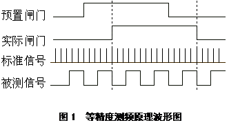
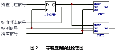
2、等精度测频法原理
等精度测频方法是在直接测频方法的基础上发展起来的。如图1所示,它的闸门时间不是固定的值,而是被测信号周期的整数倍,即与被测信号同步,其实现方式可用图2来说明。图中,预置门控信号是为Tpr 的一个脉冲,CNT1和CNT2是两个可控计数器。标准频率信号从CNT1的时钟输入端CLK输入,其频率为fs 。经整形后的被测信号(频率为fx)从CNT2的时钟输入端CLK输入,当预置门信号为高电平(预置时间开始)时,被测信号的上升沿通过D触发器的Q端同时启动计数器CNT1和CNT2计数。CNT1和CNT2分别对被测信号(频率为fx)和标准频率信号(频率为fs)同时记数。同样,当预置门信号为低电平(预置时间结束)时,随后而至的被测信号的上升沿通过D触发器的输出端,同时关闭计数器的计数。设在一次预置门时间Tpr中计数器对被测信号的计数值为Nx,对标准信号的计数值为Ns。则下式成立:
由此可推得:


3、等精度测频法具有三个特点:
(1)相对测量误差与被测频率的高低无关;
(2)增大Tpr或fs可以增大Ns,减少测量误差,提高测量精度;
(3)测量精度与预置门和标准频率有关,与被测信号的频率无关,在预置门和常规测频闸门时间相同而被测信号频率不同的情况下,等精度测量法的测量精度不变。
一种实现过程
① 预设闸门模块:由标准时钟产生预设闸门信号。如标准时钟100us[10kHz],计数1000次,产生预设闸门信号为100ms
② 实际闸门模块:用被测信号来同步预设闸门模块产生的闸门信号来产生新的实际闸门信号,本质是一个D触发器
③ 计数模块:在实际闸门信号有效时,标准时钟和被测信号同时计数,在闸门信号结束时输出计数结果
④ 频率计算模块:由公式进行乘法和除法运算
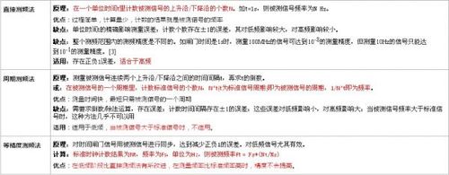
直接计数测频法
测频法原理:在确定的闸门时间Tw内,记录被测信号的变化周期数或脉冲个数Nx,有fx=Nx/Tw
测周期法原理:需要有标准信号频率fs,在待测信号的一个周期时间Tx内,记录标准频率的周期数Ns,有fx=fs/Ns
最高测量频率为标准信号频率。
测量误差:两种方法都会产生±1个字的误差。最大误差为1/N,N为周期个数。
直接计数测频法缺点:整个测频范围内的测频精度是不同的。如闸门时间是1s时,测量100MHz的信号可达到10-8的测量精度,但测量10Hz的信号只能达到10-1的测量精度。
参考信号:测频法需要得到一个标准的脉宽,测周期法需要一个标准时钟。实际上标准的脉宽必须从一个标准时钟分频得到,而一般,标准始终是从外部晶振分频得到。
测量时间:当计数周期为106个时,计数时间为1s
1、除法运算的Verilog实现(累加比较法)
2、module mydiv(clk, dataa, datab, start, datac);
input clk;
input [7:0] dataa;//被除数
input [7:0] datab;//除数
input start;//开始新的运算
output [7:0] datac;//商
reg [7:0] datac;
reg [7:0] cbuf;
reg [7:0] temp;
always @(posedge clk)
begin
if(1'b1 == start)
begin
temp <= 8'd0;
cbuf <= 8'd0;
end
else if (dataa > temp)
begin
temp <= temp + datab;
cbuf <= cbuf + 8'h01;
end
else
begin
datac <= cbuf;
end
end
Endmodule
3、直接测频法
4、闸门产生模块/gateout输出1s,clk设为1ms
module gate(clk, gateout);
input clk;
output gateout;
reg [9:0] cnt;
reg gatebuf;
assign gateout = gatebuf;
always @(posedge clk)
begin
if (10'd999 == cnt)
begin
cnt <= 10'd0;
gatebuf <= ~gatebuf; //产生1s闸门
end
else
begin
cnt <= cnt + 10'd1;
end
end
endmodule
计数模块
说明:闸门信号高有效下进行计数,当闸门信号为低时停止计数并输出计数结果。采用5位十进制计数
module cnt(clk, gate, done, dtwo, dthree, dfour, dfive);
input clk;
input gate;
output done;//个位
output dtwo;//十位
output dthree;//百位
output dfour;//千位
output dfive;//万位
reg [3:0] done, dtwo, dthree, dfour, dfive;
reg [3:0] ddone, ddtwo, ddthree, ddfour, ddfive;
reg gatebuf;
always @(posedge clk)
begin
gatebuf <= gate;
end
always @(posedge clk)
begin
if((gatebuf == 1'b0) && (gate == 1'b1))
begin
ddone <= 4'd1;
ddtwo <= 4'd0;
ddthree <= 4'd0;
ddfour <= 4'd0;
ddfive <= 4'd0;
end
else if((gatebuf == 1'b1) && (gate == 1'b0))
begin
done <= ddone;
dtwo <= ddtwo;
dthree <= ddthree;
dfour <= ddfour;
dfive <= ddfive;
end
else if(gate == 1'b1)
begin
if (ddone == 4'd9)
begin
ddone <= 4'd0;
if (ddtwo == 4'd9)
begin
ddtwo <= 4'd0;
if (ddthree == 4'd9)
begin
ddthree <= 4'd0;
if (ddfour == 4'd9)
begin
ddfour <= 4'd0;
if (ddfive == 4'd9)
begin
ddfive <= 0;
end
else
begin
ddfive <= ddfive + 4'd1;
end
end
else
begin
ddfour <= ddfour + 4'd1;
end
end
else
begin
ddthree <= ddthree + 4'd1;
end
end
else
begin
ddtwo <= ddtwo + 4'd1;
end
end
else
begin
ddone <= ddone + 4'd1;
end
end
end
endmodule
5、周期测频法
6、计数模块
module periodcnt(clk, clkt, cntout,cntok);
input clk;//标准时钟信号
input clkt;//被测信号
output [19:0] cntout;//计数结果输出
output cntok;//计数结果输出标志
reg [19:0] cntout, cnt;
reg cntok, clktbuf;
always @(posedge clk)
begin
clktbuf <= clkt;
end
always @(posedge clk)
begin
if((clkt == 1'b1) && (clktbuf == 1'b0))//在被测信号上升沿输出计数结果并置计数为1
begin
cntout <= cnt;
cnt <= 20'd1;
cntok <= 1'b1;
end
else
begin
cnt <= cnt + 20'd1;
cntok <= 1'b0;
end
end
endmodule
除法运算模块
module perioddiv(clk, datab, start, datac);
input clk;
input [19:0] datab;
input start;
output [19:0] datac;
reg [19:0] dataa,datac, databbuf;
reg [19:0] cbuf;
reg [19:0] temp;
reg finish, cntflag;
always @(posedge clk)
begin
if((1'b1 == start) && (finish == 1'b0) && (datab != 20'd0))
begin
dataa <= 1000000;
temp <= datab;
cbuf <= 20'd1;
databbuf <= datab;
cntflag <= 1'b1;
end
else if ((dataa > temp) && (cntflag == 1'b1) )
begin
temp <= temp + databbuf;
cbuf <= cbuf + 20'd1;
finish <= 1'b1;
end
else
begin
datac <= cbuf;
finish <= 1'b0;
cntflag <= 1'b0;
end
end
endmodule
7、等精度测频法
8、预设闸门模块:由标准时钟计数产生
module pregate(clk, gateout);
input clk;
output gateout;
reg gateout, gatebuf;
reg [19:0] cnt;
always @(posedge clk)
begin
if (cnt == 20'd1000)
begin
gatebuf <= ~gatebuf;
gateout <= gatebuf;
cnt <= 20'd0;
end
else
begin
cnt <= cnt + 20'd1;
end
end
endmodule
实际闸门模块:由被测信号来同步预设闸门模块产生
module actgate(clk, gatein, gateout);
input clk;
input gatein;
output gateout;
reg gateout;
always @(posedge clk)
begin
gateout <= gatein;
end
endmodule
计数模块:在实际闸门信号有效时,标准时钟与被测信号同时进行计数;在闸门信号结束时输出计数结果
module cnt(clk, gate, cntout);
input clk;
input gate;
output [19:0] cntout ;
reg [19:0] cnt, cntout;
reg gatebuf;
always @(posedge clk)
begin
gatebuf <= gate;
end
always @(posedge clk)
begin
if((gate == 1'b1) && (gatebuf == 1'b0))
begin
cnt <= 20'd1;
end
else if((gate == 1'b0) && (gatebuf == 1'b1))
begin
cntout <= cnt;
end
else if(gatebuf == 1'b1)
begin
cnt <= cnt + 20'd1;
end
end
endmodule
频率计数模块:根据公式计算
module frediv(clk, datat,datas, freout);
input clk;
input [19:0] datat;
input [19:0] datas;
output [19:0] freout;
reg [19:0] datam,freout, databbuf;
reg [19:0] cbuf;
reg [19:0] temp;
reg finish, cntflag;
always @(posedge clk)
begin
if((finish == 1'b0) && (datas != 20'd0) && (datat != 20'd0))
begin
datam <= 20'd10000 * datat;
temp <= datas;
cbuf <= 20'd1;
databbuf <= datas;
cntflag <= 1'b1;
finish <= 1'b1;
end
else if ((datam > temp) && (cntflag == 1'b1) )
begin
temp <= temp + databbuf;
cbuf <= cbuf + 20'd1;
end
else
begin
freout <= cbuf;
finish <= 1'b0;
cntflag <= 1'b0;
end
end
endmodule