含1个数统计电路设计
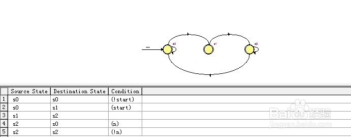
1、含“1”系统的电路控制ASM图:

2、1)控制器设计:
代码:library ieee;
use ieee.std_logic_1164.all;
use ieee.std_logic_arith.all;
use ieee.std_logic_unsigned.all;
entity one is
port(cp,start,reset,n,x:in std_logic;
cp1,cp2,o:out std_logic
);
end one;
architecture a of one is
type state is(s0,s1,s2);
signal current_st,next_st :state;
begin
process(cp,reset)
begin
if reset='1' then current_st<=s0;
elsif cp'event and cp='0' then
current_st<=next_st;
end if;
end process;
process(start,current_st,n,cp,x)
begin
case current_st is
when s0=>o<='0';
if start='1'then next_st<=s1; cp1<='0';cp2<='0';o<='1';
else next_st<=s0;cp1<='0';cp2<='0';
end if;
when s1=>o<='0';next_st<=s2;cp1<='0';
if x='1' then cp2<=cp;
else cp2<='0';
end if;
when s2=>
if x='0' and n='0' then next_st<=s2;cp1<=cp;cp2<='0';
elsif x='0' and n='1' then next_st<=s0;cp1<=cp;cp2<='0';
elsif x='1' and n='0' then next_st<=s2;cp1<=cp;cp2<=cp;
elsif x='1' and n='1' then next_st<=s0;cp1<=cp;cp2<=cp;
else next_st<=s2;cp1<='0';cp2<='0';
end if;
when others=>next_st<=s0;cp1<='0';cp2<='0';o<='0';
end case;
end process;
end a;
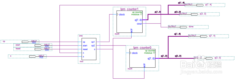
3、生成的图形模块如图:

4、整体电路的设计图:
5、系统测试 状态机模型:
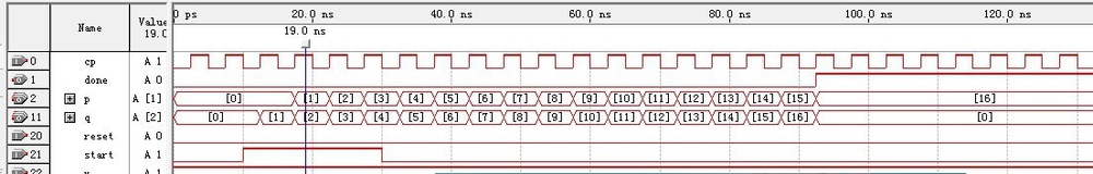
6、仿真结果